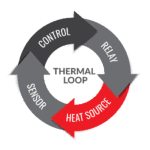
A heat trace system is a set of heated cables, accessories, and controllers designed to maintain a specific temperature. Plants and processes with piping and tanks often count on heat trace and associated insulation to keep their plants running.
Designing a heat trace system that will effectively keep all parts of the process flowing requires the correct cable, accessory set, and controller. It is also imperative to perform the correct design calculations to ensure accurate design. Using a heat trace calculator certified by IEEE 515 is the best way to ensure a proper design.
What is a Heat Trace Calculator?
A heat trace calculator is certified software that takes the details of your application and calculates what you’ll need, such as the length and type of cable required. The calculator allows users to input many variables and provides specific solutions for ordering the correct heat trace components.
A heat trace system is essential for keeping your pipes and equipment running smoothly when temperatures drop. Our heat trace experts are ready to assess your needs and provide a tailored solution to keep your process piping and equipment running this winter.
Variables Required To Design A Heat Trace
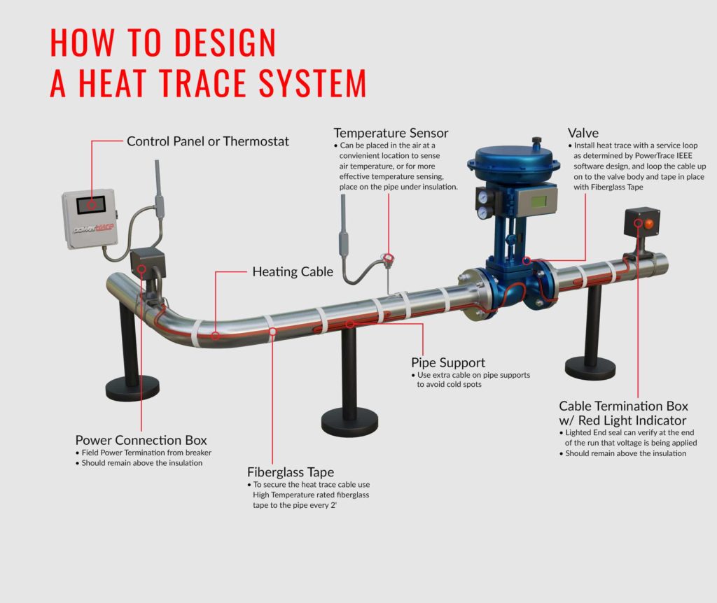
The cables are available in various wattage outputs, voltages, and jacket materials. The trace runs alongside the piping horizontally. The heat trace run will be installed at the 5 or 7 o’clock position (with the top center being 12 o’clock) at 1 foot of cable per 1 foot of pipe. Heavier valves, flanges, pumps, pipe supports, and other components are heat sinks that require additional cable to compensate for further heat loss.
A heat trace calculator will require the following inputs to provide a solution for an entire project:
- Temperature – There are seven temperature factors: maintain temperature, minimum and maximum ambient, start-up, maximum exposure, maximum operating, and maximum allowable.
- Environment – Indoor or outdoor, chemical exposure, wind speed, hazardous area classification (Class, Division, Gas, Dust, etc.)
- Piping – Type (Metal or Plastic), Composition, pipe diameter, pipe length
- Heat Sinks – Add the quantity and type of each valve, number of supports and flanges
- Insulation – Type and thickness
- Control System – Temperature control (Local thermostats or sensors and control panels)
- Electrical – Available voltage and breaker size
- End Seal Type – Choose above or below the insulation, lighted or non-lighted
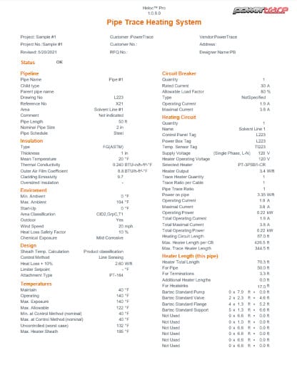
The calculator will factor in all the information and provide the necessary cable length. It also adds additional footage based on the extra heat loss caused by valves and flanges along the line. Finally, it gives a list of calculation results. A heat trace report will provide a comprehensive list of total system amperage so that you have an idea of the power consumption impact on your facility.
Below is an example of our software output.
Heat Trace Calculations – Heat Loss Formula
To calculate heat loss without a heat trace calculator, use the following formula:
| Q = | kA ΔT |
| t |
Definitions:
Q = Heat Loss
k = Insulation Thermal Conductivity
A = Area
ΔT = Tpipe – Tambient
t = Insulation Thickness
The calculator combines temperature and other factors plus the process equipment variables to provide a complete solution.
How Do You Select Heat Tracing?
A heat trace calculator will simplify determining the correct cable family and desired temperature controls for your system according to the process conditions.
Consider these factors when selecting the heat trace cable for your application:
- Maintenance temperature- at what temp does your product need to be maintained?
- Maximum exposure temperature- What is the maximum surface temperature where the heat trace attaches?
- Jacket material- if highly corrosive organic or inorganic vapors are present-what are they?
Contact your heat trace system manufacturer to choose a suitable thermostat control device.
Frequently Asked Questions
How do you calculate the heat tracing cable?
To calculate the heat tracing cable length, sum the pipe length multiplied by the number of cables, and add additional lengths for valves, flanges, power connections, splice connections, and tee connections as specified by your heat trace calculator.
How much power does electrical heat tracing use?
Electrical heat tracing typically consumes around nine watts per linear foot, but this can vary based on the specific system and environmental conditions.
What is the NEC code for heat trace?
The National Electrical Code (NEC) requires heat trace systems to be equipped with a ground fault equipment protection (GFEP) circuit breaker to ensure safety.
How many amps does a heat trace draw?
A heat trace cable generally draws up to 3 amps, with the exact current depending on the ambient temperature and system specifications.
Don't let the cold weather stop your business. Powertrace heat trace cable will keep you running smoothly no matter how low the temperatures.


